Behind the car's communication: CAN & OBD-II


When you press the accelerator, how does your dashboard know the speed? How does the engine communicate with the transmission? How does a diagnostic scanner read information from your car?
What is ECU?
An ECU (Electronic Control Unit) is essentially a small computer responsible for a particular function inside a vehicle. One ECU may manage the engine, another the brakes, another the transmission, while others handle airbags, steering, temperature and more.
These ECUs don’t work independently. They constantly exchange information, and CAN provides one of the main communication networks that makes this possible. Modern cars can have 70+ ECUs, all communicating with each other through networks such as the CAN bus.
What is CAN?
Car is overall very complex, and it has to communicate to different Electronic Control Units (ECUs) like engine, transmission, ABS, airbags, dashboard, doors, battery system etc. All these devices need to talk to each other to work properly and function as programmed.
CAN (Controller Area Network) is a message-based protocol, used in vehicles, to provide reliable communication between multiple Electronic Control Units (ECUs). CAN is like a nervous system which connects all body parts together.
			CAN BUS
     ─────────────────────
       |       |       |
    Engine     ABS   Dashboard
      ECU      ECU      ECU
CAN is a shared line where every ECU broadcasts messages, and every other ECU on the bus can hear them. Nobody sends a message to one specific device, everyone hears everything, and each ECU decides for itself whether a message is relevant.
Physically, this runs on two wires: CAN High and CAN Low. Data travels as the voltage difference between them, which is why it’s called differential signaling. This design is what makes CAN resistant to electrical noise, something that matters a lot inside a vehicle full of motors and ignition systems.
ABS ECU: Anti-lock Braking System It is a crucial component in modern vehicles. It is responsible for preventing wheel lockup during emergency braking, maintaining steering control, and reducing stopping distances.
What does a CAN message look like? CAN Data Frame Structure

CAN frame as a small message sent between ECUs. For example, suppose the car wants to share its speed:
"Vehicle speed = 50 km/h"The CAN bus doesn’t send this sentence. It converts the information into a structured frame containing an ID, data, error-checking information, and control bits. A simplified CAN frame looks like this:
SOF → ID → Control → DLC → DATA → CRC → ACK → EOF1. Start of Frame (SOF): The SOF tells all ECUs “A new CAN message is starting.” It is 1 dominant bit (0). It’s like an alert “Attention, new message!”
SOF = 02. CAN ID: It identifies the message and also determines its priority. For example:
ID: 0x123The vehicle might define 0x123 as a message related to vehicle speed. Another message could be:
0x200 → Engine RPM0x300 → Steering informationThe exact meaning of these IDs depends on the vehicle manufacturer. For a Standard CAN frame, the ID is 11 bits, giving IDs from:
0x000 → 0x7FF3. RTR (Remote Transmission Request): tells us whether the frame is carrying data or requesting data.
For a normal data frame: RTR = 0
For a remote frame: RTR = 1
4. DLC (Data Length Code) tells the receiver how many bytes of data are coming. Eg:
DLC = 2means: “The next field contains 2 bytes of data.” Classic CAN can carry up to 8 bytes of data.
5. Data: Actual Information. This is the most important part.
Suppose the vehicle sends:
ID:    0x123
DLC:   2
DATA:  01 F4
The two data bytes are: 01 F4
But these bytes don’t automatically mean “50 km/h.” The vehicle manufacturer defines how they should be interpreted. For example, if the specification says:
Speed = raw value × 0.01then:
0x01F4 = 500500 × 0.01 = 5 km/hSo, the message could represent: Vehicle speed = 5 km/h
The important thing is: CAN carries bytes. The vehicle’s CAN specification tells us what those bytes mean.
6. CRC (Cyclic Redundancy Check) Tells us is the Message Correct? The receiver checks did this message arrive correctly, or was something corrupted while travelling across the bus? If the check fails, the frame is treated as having an error.
7. ACK(Acknowledgement): Confirmation from the receiving nodes. The transmitter sends a recessive bit, and a node that successfully receives and validates the frame overwrites the ACK slot with a dominant bit. In simple terms: “I received the message correctly.”
8. EOF (End of Frame) tells the nodes that this CAN message is finished. It consists of 7 recessive bits. After the required intermission, the bus can be used for another frame.
SOF  → New message is starting
ID   → This is message 0x123
DLC  → I have 2 bytes of data
DATA → 01 F4
CRC  → Check that the message is correct
ACK  → A receiver successfully received it
EOF  → Message is finished
So, a message might look like 0x123 carrying 11 22 33 44. On its own, that string of hex means nothing. Figuring out what it maps to RPM, speed, door status is a separate exercise, and I'll come back to that.
Who Gets to Talk First
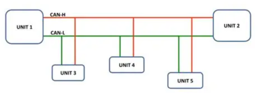
Since every ECU shares the same line, there has to be a rule for what happens when two ECUs try to send a message at the same moment. CAN solves this with something called arbitration, and it’s genuinely one of the more elegant parts of the protocol.
Lower CAN ID numbers win. If ECU A sends 0x100 and ECU B sends 0x200 at the same instant, 0x100 gets priority and goes through first, while 0x200 waits its turn. This happens automatically at the electrical level, no central controller is deciding anything, the bus itself resolves the conflict bit by bit.
This is also why safety-critical messages like an airbag trigger, are usually assigned lower IDs.
A few things to note:
The sensor itself has no idea what CAN is. It just produces a raw signal.
The ABS ECU reads that signal, computes a value, and hands it to its CAN controller, a small hardware block whose entire job is building and parsing CAN frames, timing, bit stuffing, CRC, all of it.
The CAN transceiver is a separate physical chip that converts the controller’s digital signal into the actual differential voltage on CAN_H and CAN_L. This is the part actually touching the wires.
Every other ECU on the bus receives the exact same electrical signal. Their own CAN controllers use hardware filtering to check the ID against a list of IDs they care about and silently discard everything else. This filtering is what makes CAN scale. An ECU isn’t burning CPU cycles processing messages it doesn’t need.
Only once an ID passes the filter does the message reach application logic, the code that actually decides what to do with a speed value.
This same layered architecture appears in development boards such as ESP32-based CAN setups: the application interacts with a CAN controller, while a CAN transceiver handles the electrical communication over CAN_H and CAN_L.
Where OBD-II Comes In
Here’s something that trips people up early on, and it tripped me up too.
CAN is the communication protocol, the language ECUs used to talk to each other. OBD-II, On-Board Diagnostics II, is a standardized vehicle diagnostic system. Since the mid-1990s in the US (and later elsewhere), every vehicle has been required to expose this port, originally meant so mechanics could plug in a scanner and pull fault codes without having to know the internal wiring of every manufacturer’s system.
Modern vehicles commonly use CAN as the underlying communication protocol for OBD-II diagnostics. This means that when you connect a compatible diagnostic tool to the OBD-II port, the tool can communicate with the vehicle using CAN-based diagnostic protocols.
OBD-II
   ↓
Diagnostic interface
   ↓
Possible communication protocols
   ↓
CAN / ISO 15765-4
The port itself is a 16-pin connector, and only a few pins matter for CAN access:


Exploring CAN Without a Real Car
Now that we understand how CAN and OBD-II are connected, we can take the next step and experiment with CAN traffic. The good part is that we don’t need a car or expensive hardware for this. Linux provides a Virtual CAN (vCAN) interface that lets us create a simulated CAN bus.
Creating a Virtual CAN Bus
On Kali Linux, we can create vcan0 using:
sudo modprobe vcan
sudo ip link add dev vcan0 type vcan
sudo ip link set up vcan0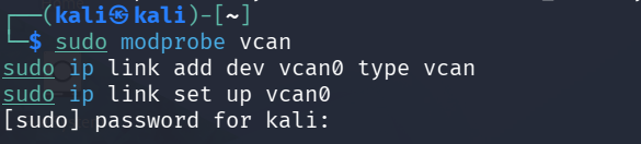
Here, vcan0 acts like a CAN bus, but it exists completely in software. This means we can send, receive and analyse CAN frames without connecting to an actual vehicle. Once it is running, we can check the interface with:
ip link show vcan0Sending a CAN Message
We can use cansend to manually create a CAN frame:
cansend vcan0 123#1122334455667788
cansend vcan0 123#1122334455667799
cansend vcan0 123#1122334455667722
Here:
vcan0 is our virtual CAN interface.
123 is the CAN ID.
# separates the ID from the data.
11 22 33 44 55 66 77 88 are the 8 data bytes.
So, we have created a CAN message ourselves. To continuously generate random CAN traffic, we can also use:
cangen vcan0This is useful for testing CAN monitoring tools because it produces a stream of frames without needing a real vehicle.
Reading CAN Traffic
To see what is travelling through the virtual bus, we can use:
candump vcan0For example:
vcan0 123 [8] 11 22 33 44 55 66 77 88This tells us that a frame with ID 0x123 carrying 8 bytes of data was received. At this point, we can see the messages, but we still need to make sense of what the data represents.
Turning CAN Data into Vehicle Information
For a simple demonstration, let’s create our own simulated vehicle-speed signal. We’ll define:
CAN ID: 0x100
Meaning: Vehicle Speed
Formula: Speed = raw value × 0.01
If the raw value is 5000: 5000 × 0.01 = 50 km/h
We can send this simulated speed using:
cansend vcan0 100#8813000000000000The important thing here is that we are defining this mapping ourselves for the demonstration. In a real vehicle, the meaning of each CAN ID and its data bytes depends on the vehicle’s communication specification.
Reading It with Python
Instead of manually looking at hexadecimal values, we can use Python to read and decode the message.
First, we use the python-can library:
python3 -m pip install python-can
nano speed_reader.py

# Run this after adding code in your file
python3 speed reader.py
import can
# Imports the python-can library so Python can work with CAN messages.

bus = can.Bus(
    interface="socketcan",   # Uses Linux's CAN interface
    channel="vcan0"          # Connects to our virtual CAN bus
)

print("Listening for vehicle speed...\n")

for message in bus:
    # Continuously waits for and reads incoming CAN messages.

    if message.arbitration_id == 0x100:
        # Only processes messages with CAN ID 0x100.
        # We have defined 0x100 as our vehicle-speed message. It is our example mapping, not a universal CAN ID.

        raw_speed = int.from_bytes(
            message.data[0:2],
            byteorder="little"
        )
        # Takes the first 2 data bytes and converts them into a number.

        speed = raw_speed * 0.01
        # Converts the raw value into km/h using our defined formula.

        print(f"CAN ID: 0x100 | Vehicle Speed: {speed:.2f} km/h")
# Displays the CAN ID and calculated vehicle speed.message.data[0:2]: Slices the first two bytes (Byte 0 and Byte 1) out of the CAN message payload.byteorder="little": Specifies Little-Endian byte order (Least Significant Byte first). If Byte 0 is 0x34 and Byte 1 is 0x12, Python recombines them as 0x1234 ($4,660$ in base-10) rather than 0x3412{speed:.2f}: Formats the floating-point speed to two decimal places
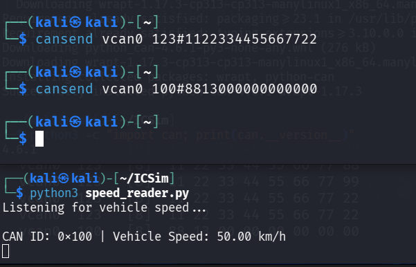
This is the basic idea behind CAN data analysis: the raw CAN frame is only the starting point. The real challenge is understanding what those bytes represent.
So, where are we?
Once we can generate and interpret CAN traffic, the cybersecurity side becomes much more interesting.
CAN was designed mainly for reliable communication between trusted vehicle components. It does not inherently provide features such as sender authentication or encryption.
This raises questions such as:
What happens if someone injects an unexpected message?
What if a valid message is captured and replayed?
Can abnormal CAN traffic be detected?
and many more ofc.
These can be explored from both sides of automotive cybersecurity: attack and defense.
I may take this further as a small project in the future, although I haven’t decided on the exact direction yet. It would be interesting to build something where the same CAN environment is used to demonstrate how it works.


Comments