Behind the Car’s Communication (II): CAN Transceiver
- Aastha Thakker
- 5 minutes ago
- 6 min read


In my last blog, I explained how CAN and OBD-II let a car’s ECUs talk with each other and how a scan tool listens in. What I skipped over on purpose is the tiny chip that makes any of that possible: the CAN transceiver. Without it, your microcontroller is basically shouting into a wall.
This is what a CAN transceiver looks like:

The Translator
Your ESP32 has a CAN controller built in, on ESP32 it’s called TWAI. That controller understands the CAN protocol perfectly: frame structure, arbitration, error handling, all of it (explained here). But it only speaks in logic-level voltages (0V and 3.3V). Plain digital.
The actual CAN bus doesn’t work that way. It runs on two wires, CAN-High and CAN-Low, and it encodes bits as the difference between those two voltages, not as a single high/low signal. That’s a completely different language, and your microcontroller has no idea how to speak it.
That’s the whole job of a transceiver: sit between the controller and the bus and convert.
Dominant, recessive, and why the voltages look weird
I covered dominant and recessive bits before. A dominant bit (logic 0) wins arbitration over a recessive bit (logic 1). Here’s what that actually looks like electrically:
Recessive state: CAN-H and CAN-L are close to the same voltage, often around the transceiver’s common-mode level. For many 5V CAN transceivers, this is roughly around 2.5V on each line.
Dominant state: the transmitting transceiver drives CAN-H higher and CAN-L lower, creating a differential voltage between the two lines.
These numbers are examples, not universal CAN voltages. The actual values depend on the transceiver, supply voltage, load, termination and other conditions.
And this is the important part: the receiver isn’t simply asking, “Is CAN-H 3.75V?” It is looking at the relationship between the two lines.
If:
CAN-H ≈ CAN-L
the bus is in the recessive state.
If:
CAN-H > CAN-L
by the required differential amount, the bus is in the dominant state.
Here’s the part that made it click for me: the receiver on the other end never looks at either wire on its own. It only measures the difference between CAN-H and CAN-L. That’s called differential signaling, and it’s the reason CAN survives sitting a few inches from an alternator, spark plugs, and a dozen motors without corrupting data, electrical noise usually hits both wires equally, so it cancels out when you subtract one from the other.
Picking a transceiver for your own build
Which transceiver to choose actually?
So, I have two controllers, ESP32 and NodeMCU ESP8266. If you’re using an ESP32, a 3.3V-compatible transceiver like the SN65HVD230 is a convenient choice; if you’re using a NodeMCU ESP8266, you’ll need an external CAN controller such as the MCP2515, usually paired with a CAN transceiver on the module. Choose the setup based on the controller you already have.

The important thing to understand is that the ESP32 and the CAN bus speak two different electrical languages. The ESP32 works with 3.3V digital logic, while the CAN bus uses the differential CANH and CANL lines. The transceiver sits between these two sides and converts the signals.
So, when choosing one, mainly look at logic voltage compatibility, CAN bus compatibility, and how easily it can connect to the microcontroller.
1. SN65HVD230 (a convenient choice for 3.3V microcontrollers):
The SN65HVD230 is a popular CAN transceiver for projects using 3.3V microcontrollers such as the ESP32. Its logic-side pins, TXD and RXD, are designed to work with 3.3V logic. This means you generally don’t need to add a separate logic-level shifter just to connect the ESP32 to the transceiver.
Another useful feature is its low-power standby mode, which can be useful in battery-powered or automotive projects where power consumption matters.
For my ESP32-based CAN experiments, this makes the SN65HVD230 a practical choice because the logic voltage matches the microcontroller and the wiring stays simple.
2. MCP2551 (widely used, but pay attention to voltage):
The MCP2551 is another well-known CAN transceiver. It performs the same basic job: it takes logic-level CAN signals from the controller and converts them into the differential signals used on the CAN bus.
The important difference for an ESP32 project is its 5V supply and logic-level requirements.
An ESP32 uses 3.3V GPIO. So, you should not simply assume that a 5V CAN transceiver can be connected directly to every ESP32 pin. Depending on the exact circuit and signal direction, the voltage levels need to be checked carefully, and level shifting may be required.
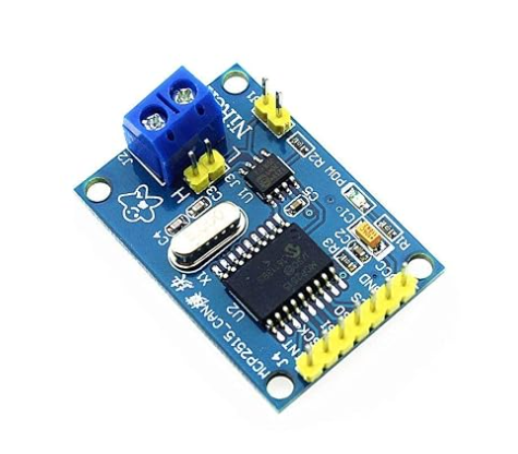
One thing that often causes confusion is the difference between a CAN controller and a CAN transceiver. The MCP2515 is a CAN controller, while the MCP2551 is a CAN transceiver. The controller handles the CAN protocol and communicates with the microcontroller, typically over SPI.
The transceiver handles the physical side of the connection, converting the controller’s signals into the differential CANH and CANL signals used on the bus. They can therefore work together as MCP2515 + MCP2551 to form a complete CAN node. In fact, Microchip documents this exact combination in its MCP2515 CAN development hardware.
What else the CAN bus needs
A transceiver alone can’t run a bus. Three more things have to be right, or that rope never settles into a usable signal.
Termination resistors (120Ω at each physical end)

120k Ohm (Ω) 1/4w (0.25 watt) ±5% Tolerance 120k MR Ω ohm MF Through Hole Resistors Axial Lead
CAN is designed as a bus, not a collection of point-to-point connections. Because the CAN signals travel along the physical wiring, the ends of the bus need to be properly terminated. A typical high-speed CAN network uses 120Ω termination resistors between CAN-H and CAN-L at the two physical ends of the bus.
Why?
When an electrical signal reaches the end of a transmission line, part of the signal can be reflected back. These reflections can distort the original signal and cause communication errors, especially as the bus gets longer or the communication speed increases. The termination resistors help match the electrical characteristics of the bus and reduce these reflections.
One important detail: you normally don’t put a 120Ω resistor on every CAN node. There should generally be one at each physical end of the main bus.
If you measure the resistance between CAN-H and CAN-L on a powered-down, correctly terminated bus, the two 120Ω resistors appear in parallel, so you will typically measure around 60Ω.
2. What about bias networks?
You may come across CAN circuits using split termination or other biasing arrangements. These can help control the common-mode behavior of the bus and improve EMC, but they are not mandatory for every high-speed CAN network.
The exact termination and biasing arrangement depends on the transceiver and the particular CAN network. For a basic setup, don’t assume that every CAN bus needs an extra bias network; check the transceiver’s datasheet and the network design.
So, don’t look at a CAN circuit and assume that every bus must have an extra “bias network.” Instead, check the transceiver’s datasheet and the requirements of the particular CAN design.
3. A shared ground (reference point)
CAN mainly determines the bus state from the voltage difference between CAN-H and CAN-L, but that doesn’t mean ground is irrelevant. Each CAN transceiver operates within a specified common-mode voltage range. If two non-isolated CAN nodes have significantly different ground potentials, communication can become unreliable or the transceiver can be pushed outside its allowed operating range.
For a simple non-isolated setup, connecting the GND of the CAN nodes together is generally good practice.
Automotive systems can be more complicated because of ground offsets, electrical noise, and galvanic isolation. But for a basic ESP32 CAN experiment, a common ground is the practical approach.
Get the physical-layer basics wrong and you can end up with symptoms that look confusing if you don’t know the cause: reflections that corrupt frames, unexpected common-mode voltages, or nodes that simply fail to communicate even though the individual chips appear to be working fine.
Wrapping up here
Honestly, transceivers are one of those topics that feel more confusing the moment you actually open a datasheet like differential voltages, bias networks, termination math, it stacks up fast. This post is only the surface layer, on purpose. I’m keeping this series to the basics, enough to understand what’s happening on the wire and enough to not fry a chip or your brain.
There’s a lot more underneath all these. This is genuinely just the beginning. If any part of this post felt like a lot, that’s fair, sit with it, come back to it, and it’ll click faster than you’d expect once you see it on real hardware.
More soon.


Comments